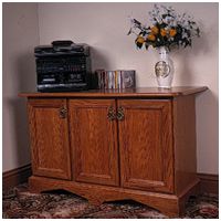
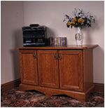
Woodworker Of The Year finalist, James Brolly, builds a stereo cabinet
You've got to start somewhere, so I started by lipping the top of the cabinet, beginning with the ends and then the front and back, using a biscuit about every 100mm for added strength. When the glue had dried, I trimmed up and radiused the front corners using a template and a panel-trim cutter in the router. Then, using a bearing-guided rounding-over cutter, I moulded the front and both side edges.
In between the lipping operations, I began work on the carcase sides by lipping the front and back corners. The rear has a 50 x 19mm solid lipping, set at 90¡, and the front is 30 x 19mm set in line. Both of these extend below the panel to form legs, to which the plinth will eventually be fixed. The back lippings can be mortised for the back rails before gluing in place if this is preferred.
I then removed most of the waste with the router inverted in the table, and finally trimmed up using a sharp chisel. I assembled it using Cascamite, taking care to ensure that it stayed flat and square while the glue dried, as any deviation would be impossible to rectify later.
I then cut the two back rails to length, and cut the tenons and I was ready to assemble the carcase. I used biscuits to join the front frame to the sides, and having carefully measured and trimmed the legs to length, I made a dry run to ensure that everything would go together without problems.
I then glued up and clamped, keeping it on a flat surface, and making sure it stayed square. I next moulded the stock for the door frames (see fig 3) and door section using the router in the table. I used an ogee cutter for the inner edge, with a point round-over on the front face. I used a straight cutter to cut a rebate for the glass or panel, and finally a roundover for the outer front corner.
To cut the slots, I carefully marked each piece, secured the biscuit jointer in the vice by the handle, and bring the work to the biscuit jointer. Care must be taken with the grip on the workpiece, but I find this method easier for mitred pieces of this size, and as safe as any other if done carefully. (I only glue one frame at a time as I've only got one frame cramp, so the assembly is done over several days).
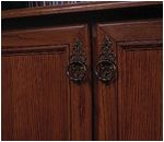
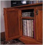
To fit the doors I use piano hinges, cutting a mortise the full depth of the hinge in the cabinet stiles. This means that there is no need to mortise the doors, and small adjustments can be made by first fixing with two screws only, then if slight re-alignment is necessary, new unused holes can be used, and when satisfied, all screws can be inserted. Holes should be pre-drilled. Handles and catches are fitted at this stage as access is easy without the top. I use double ball catches. The doors and all fittings are then removed until after staining and finishing.
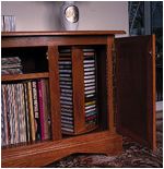
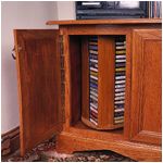
I joined two pieces of MDF, both 495mm long, one 126mm wide and the other 106mm wide, along the long edge using a box joint, which I cut by hand. This gave me an L-shape with sides of 100mm and 120mm using 6mm MDF, and a height of 495mm. I made eight of these, for two carousels.
When these were dry, I formed a tenon at each end of each one, by taking 6mm off the length, starting at the outside edge, and working in towards the joint for 50mm on the 100mm side and 70mm, on the 120mm side. This will leave a tenon 6mm long and 50mm wide, which will fit into through mortises in the top and bottom pieces (fig 1a).
I then sized two pieces of softwood to 20mm square and 550mm long, one for each carousel, and laid them to one side while I cut the tops and bottoms. These were also made from 6mm MDF, all four are identical, and start with a piece 280mm square. I mortised them as shown in fig 1a, with a 20mm hole in the centre, and four L-shaped cut outs as shown, to suit the tenons already mentioned. I rounded the shape at the corners, taking care not to weaken it too much near the mortises, and was ready to assemble. With glue and screws I fixed the L-shapes to the softwood cores as shown in fig 1a, and then glued the ends in place.