 |
Shop tip |
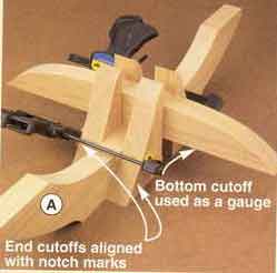
| Let cutoffs be your guide Want to get some mileage from your cutoffs? To cut the notch in the feet (A), you'll need to use a handsaw. Master Craftsman Chuck Hedlund used the odd-shaped foot cutoffs as saw guides to get exact-width notches in both feet. The photos, below, show you how to doit. |
|
 |
|
| Align the end cutoffs with a foot's notch marks, place
the bottom cutoff between them as a gauge, and clamp the end cutoffs to
the foot. |
|
 |
|
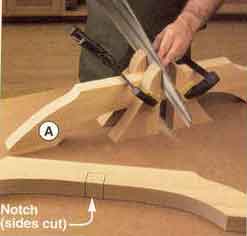
| With the bottom cutoff removed, cut the sides of the
notch, keeping the saw tight against the end cutoffs. |
|
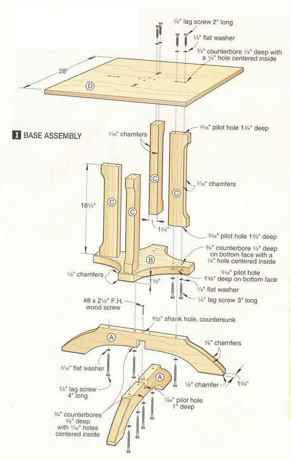
| Get moving on the feet 1 From 1 3/4"-thick oak, cut the feet (A) to the size listed in the Materials List. As an alternative, you can laminate thin-ner stock, and plane it to 1 3/4" thick. 2 Make four copies of the full-size foot end pattern on the WOOD Patterns® insert. Spray-adhere the pat-terns to the feet, where shown on the pattern's diagram. (Flip the pattern over at one end of each foot.) Draw a straight line connecting the patterns' bottom lines together. Now, lay out the notches on the feet, where dimensioned on the pattern. 3 Bandsaw and sand the feet to shape, saving the cutoffs. Using a handsaw and the cutoffs as a guide, as explained in he Shop Tip, above, cut the sides of the notches. Then, chisel out the waste. 4Chamfer the feet's edges, where shown on the pattern. Then, remove the patterns, and sand the feet to 220 grit. Glue and assemble the feet; drill the countersunk shank hole through the notch joint, where shown on Drawing 1; and drive the screw. |
|
 |
 |
|
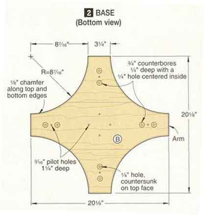
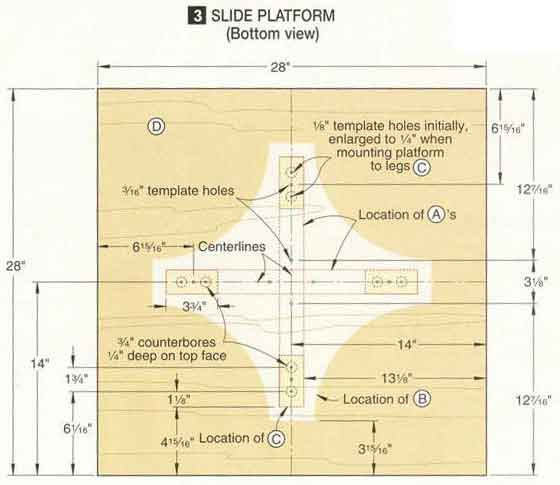
Next up: the base, legs, and slide platform 1 Edge-join enough 1 1/2"-thick oak to form a 21x21" workpiece for the base (B). Then, trim the base to finished size. 2 Mark the four radii on the base, where dimensioned on Drawing 2. Bandsaw and sand the base to shape. Now, rout Vi" chamfers along the base's top and bottom edges. 3 Next, cut the legs (C) to size. Make two copies of the full-size leg end pattern, and spray-adhere them to the ends of a leg. Draw a line to connect the patterns together. Now, bandsaw and sand the leg to shape, and remove the patterns. Using this leg as a template, mark the other legs, and cut and sand them. Then, rout 1/16" chamfers along the legs' edges. 4 Cut the slide platform (D) to size. From scrap 3/4" plywood, cut another piece to the same size. (You'll use it when assembling the table's base.) 5 To prepare the slide platform for use as a drilling template, draw a pair of centerlines on its bottom; lay out the locations for parts A, B, and C; and mark the hole locations, where dimensioned on Drawing 3. Then, drill 1/8" and 3/16" holes through the platform, where shown. Turn the platform over, and counterbore the 1/8" holes. 6 For matching purposes, number the leg (C) locations (the order is not important) on the platform's bottom, and number the legs. Also, mark a "1" on a foot (A) and on an arm of the base (B) to index these parts to the platform. |
 |
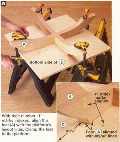
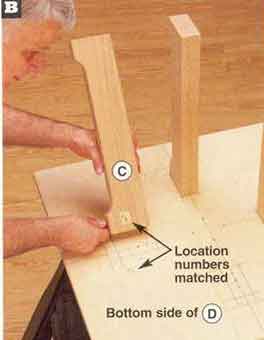
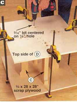
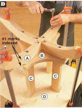
| Drill lag-screw holes, and assemble the base Note: To successfully do the operations in this section, you need to pay close attention to the orientation of parts and the applicable sets of holes in the slide plat-form (D) that you'll use as drilling guides. To ensure success, read through the sec-tion first, and make sure you understand all of the steps before proceeding. 1. To drill the counterbored holes in the feet (A) for lag screws, where shown on Drawing 1, place the slide platform (D) on sawhorses with the bottom side up. Then, align and clamp the feet to the plat-form, as shown in Photo A. 2 Turn the clamped assembly over. Using the eight -3/16" holes in the plat-form as guides, drill 3/16" holes as deep as you can into the feet. Remove the platform. Now, redrill the holes with а 7/16" bit, bor-ing through the feet. 3Place the feet on your drill-press table with the bottom face up. Using a 3/4" Forstner bit, counterbore the four inner holes 3/8" deep. Set the depth stop to ensure a consistent depth. Without changing the setting, counterbore the four outer holes. 4 To align the base (B) on the platform for drilling, mark centerlines across the grain on the ends of the base's arms. Apply a few pieces of double-faced tape to one face of the base. Indexing the base to the platform, align their centerlines, and press the base firmly against the platform. 5Turn the assembly over. Using the 3/16" holes in the platform as guides, drill -3/16" pilot holes 1 1/4" deep in the base's bottom. See Drawing 2. Then, using the 1/8" holes in the platform as guides, drill 1/8" holes through the base. Remove the base from the platform. 6Using the 3/4" Forstner bit in your drill press, counterbore the 1/8" holes in the base's bottom 1/4" deep. Then, enlarge the 1/8" holes to 1/4" . Now, coun-tersink the (1/4" holes on the base's top, where shown. This will ensure a tight fit when the base is attached to the legs (C). 7 To drill the pilot holes in the ends of the legs, place the platform on the sawhorses, bottom face up. Align the legs on the platform, as shown in Photo B. Then, place the 3/4x28x28" piece of scrap plywood on top of the legs, in line with the platform, and clamp the assembly together. Double-check the alignment of the legs on the platform. 8 Place the clamped assembly on the floor with the platform on top. Using the 1/8" holes in the platform as a guide, drill pilot holes in the legs, as shown in Photo С. Unclamp the assembly, turn the legs over end for end, reclamp with the legs aligned as before, and drill the pilot holes. Now, centering on the -3/16" holes you just drilled, drill 1/4" holes 3/4" deep in the platform for shank holes. 9 Drive 1/4" lag screws 2" long with 1/4" flat washers through the platform and into the legs. To ease installation, lubricate the threads with paraffin. 10 Place the assembly back on the sawhorses with the scrap ply-wood on top. Remove the plywood. Index and position the base (B) bottom face up on the legs, aligning the base's and legs' holes. Now, clamp the assem-bly together, and drive 1/4" lag screws 3" long with 1/4" flat washers through the base and into the legs. 11 Unclamp the assembly. Mount the feet (A) on the base (B), as shown in Photo D, and drive the1/4" lag screws 4" long with -5/16" flat washers. |
Match the legs (C) to the numbered locations on the slide platform (D). Align the legs with the layout lines. |
 |
|
| Centering a 3/16" bit on the platform's 1/8" holes, drill a pair of 1 3/4-deep pilot holes in each leg (C). | |
 |
|
| Index the feet (A) on the base (B), and align their mounting holes. Clamp the assembly, and drive the lag screws. | |
|
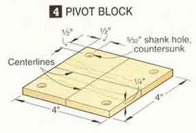
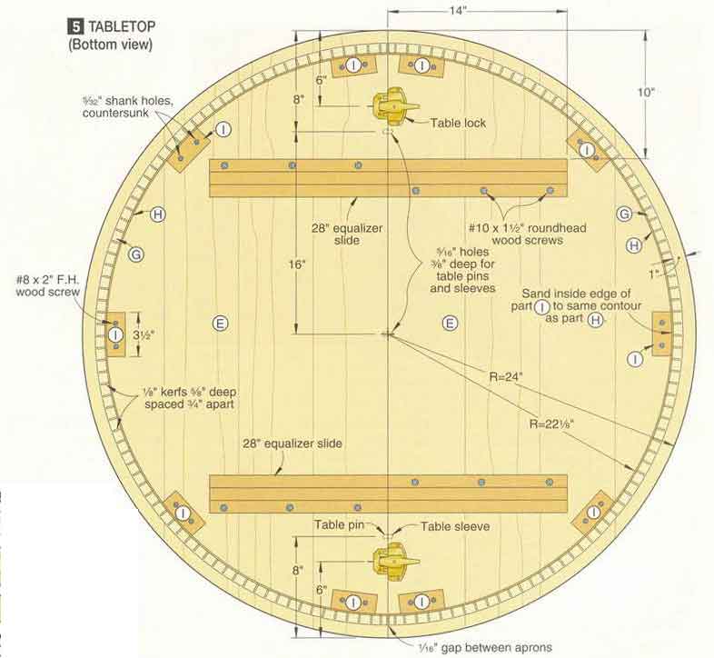
Make the tabletop and leaves 1 Edge-join enough 3/4"-thick boards to make two 25x49" workpieces for the tabletop halves (E) and two 13x49" workpieces for the leaves (F). Rip the leaves to their finished width of 12". 2 Using a square, mark a centerline across the width of the tabletop halves and leaves on their bottom faces. Then, place the tabletop halves (not the leaves) bottom face up on your workbench with the centerlines aligned. Apply two pieces of duct tape across the joint to keep the parts tight together and aligned. 3From scrap, make a pivot block for marking (and later routing) the table-top's diameter, as shown on Drawing 4. Mark centerlines across the block's face and down its edges, where shown. 4Center the block on the tabletop's bottom face, aligning the block's centerlines with the tabletop's centerline and joint line. Fasten the block to the tabletop with four #8x1/2" flathead wood screws. Then, using a trammel, and locating its pivot pin on the block's center, draw a circle with a 24" radius for the top's outer edge and another circle with a 22 1/8" radius for locating the glue blocks (I), where shown on Drawing 5. Remove the pivot block. |
 |
 |
| 5 Using a straightedge,
draw lines across the tabletop's joint to mark the locations for the
outer tabletop pins/sleeves and the table locks, where dimensioned. (The
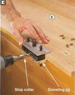
center pin and sleeve align with the tabletop's centerline.) 6 To mark the locations for the leaves' pins and sleeves, position the leaves between the tabletop halves, align the parts' centerlines, and tape across the joints. Then, align a straightedge with the marked lines on the tabletop halves for the outer pins and sleeves, and draw lines across the leaves' joints. To ensure correct pin installation, mark "pin" on the right side of the left tabletop half and leaves. Separate the parts. 7 Using a doweling jig, drill 5/16" holes 3/8" deep in the parts' edges at the marked locations, as shown in Photo E. Then, install the pins and sleeves in the applicable holes, using a mallet to drive them in. 8 Using a helper, bandsaw and sand the tabletop halves to within 1/8" of the outer line. Then, join them together, bottom face up, and tape across the joint. Now, using a 1/2" straight bit in your router and a router trammel, trim the top to the line. For help on doing this, see the sidebar, opposite page, far right. |
 |
|
| 9 To trim the leaves'
lengths, position the leaves tight between the top halves. Now, using a
straightedge aligned flush with the tabletop halves' edges, draw lines
across the leaves. Cut and sand the leaves to the lines.
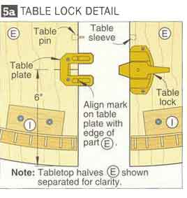
10 To install the table locks, join the tabletop halves (E) together, bot-tom face up. On the tabletop half with table pins, position the table-lock plateswhere shown on Drawing 5a, centering them on your marks. Mark the mounting hole locations, drill pilot holes, and drive the supplied screws. Then, position the mating table locks on the other top half, and engage them with the plates. Mark the table locks' mounting holes, drill the holes, and drive the screws. |
 |
 |
| 3 steps to routing large circles | ||
 |
 |
 |
| Align a doweling jig's 5/16" guide hole with the marked
line for a pin or sleeve. Adjust the jig to center the guide hole on the
part's edge, and drill the hole. |
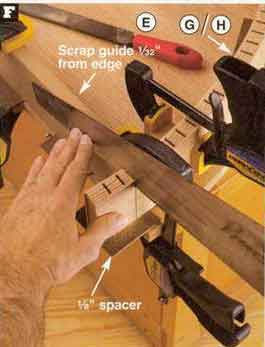
Clamp а 3/4х3 1/2х18" scrap to the tabletop half, 1/32 "
back from its straight edge and tight against the apron. Using the scrap
as a saw guide, trim the apron's end. |
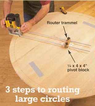
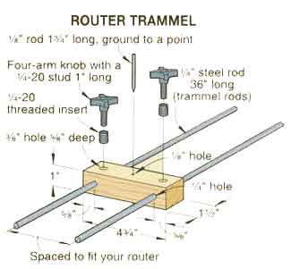
With just a router, a straight bit, and a router trammel, you can easily form large, perfectly circular parts, such as this project's tabletop. No trammel? Don't worry. In a flash, you can make the one shown in the drawing, below, that will let you cut circles up to 72" in diameter. Here's how to put the setup to work. |
| 11 Place a leaf (F), bottom face up, between the tabletop halves. Then, position table locks and plates on the leaf, and engage them with the mat-ing parts on the tabletop halves. Screw the parts to the leaf. Insert the remaining leaf, and install its lock hardware in the same way. Remove the leaves, and join the tabletop halves together.
Add the aprons Note: As an alternative to forming the tabletop's curved aprons (parts G and H, shown on Drawing 5), you can use preformed parts. (See the Buying Guide at the end of this article for our source.) These parts have predrilled pocket holes, so you'll screw them directly to the tabletop halves (E) without using glue blocks (I).
|
||
| STEP1 Insert and fasten the trammel's rods in your router's edge-guide mounting holes. Then, set the radius of the circle by measuring from the inside of the straight bit's cutting edge to the center of the trammel's pivot pin. Now, lock in the radius by tightening the trammel's knobs. STEP 2 Drill a hole, sized to suit the trammel's pivot pin, in the center of the workpiece's bottom. Make the hole at least 1/4" deep but not through the workpiece. Or, for this project's tabletop, which has a joint between the halves (E), drill a hole through the scrap pivot block's center, and reattach the block to the tabletop's bottom. STEP3 With the workpiece rough-cut to within 1/8" of the finished diameter, insert the jig's pivot pin into the drilled hole. Now, plunge the router bit, and slowly rout the workpiece, as shown in the photo, above. |
||
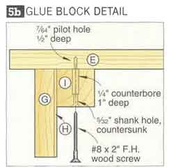
| 1. Cut the kerfed aprons (G) to the listed width but to a length of 75 5/8", and cut the apron backers (H) to width but to a length of 73". Then, referring to the article on page 22, kerf the aprons, assemble the backers to them, and form the assemblies to the radius shown on Drawing 5.
2 Cut the glue blocks (I) to size, and
drill the blocks' countersunk shank holes, where shown on Drawings 5 and
5b. Turn the blocks over, and counter-bore the holes. Set eight of the
18 blocks aside for the leaves (F). To radius an edge of the remaining
10 blocks so they fit tight against the curvature of the apron/backer
assemblies (G/H), use an apron as a template, and scribe its con-tour on
a block's face. Sand the block to the line. Now, using this block as a
tem-plate, mark the other blocks, and sand them to shape. |
 |
|
| 6 Remove the aprons. Apply glue to the glue
blocks' curved faces. (We used Titebond Wood Molding Glue, which sets
quickly and helps to fill any gaps between the parts.) Clamp the aprons
to the blocks. 7 Cut the leaf aprons (J) to size. Then, glue the blocks (I) to the aprons, flush with their ends, where shown on Drawing 6. 8 Position the tabletop-half assemblies (E/G/H/I), with the leaves (F) between them, bottom face up. Then, along each side of the table, place a straightedge against the aprons (G/H), and draw a line across the leaves. Align the block/apron assemblies (I/J) with the lines, and center them side-to-side on the leaves. Drive the screws through the blocks and into the leaves. 9 Rout a 1/16" chamfer along the outside edge of the table's aprons. Then, remove the leaves, and rejoin the top. |
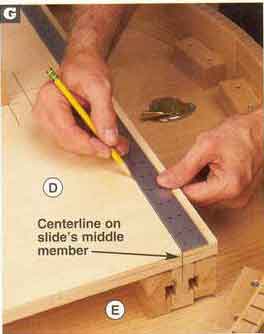 |
| Complete the assembly, and finish up 1 To install the 28" equalizer slides, where shown on Drawings 5 and 7, make marks on the bottom face of the tabletop halves (E) 10" in from the ends of their straight edge. Then, using a square, extend a 14" line from each mark. 2 With the predrilled, countersunk holes in the slides' outer members faceup, position and align the slides on the inside of the marked lines, where dimensioned on Drawing 5. Then, using an awl, mark the slides' hole locationson the tabletop. Remove the slides, and drill a 1/8" pilot hole 5/8" deep at the marked locations. Now, realign the slides, and drive the screws. 3 Position the base assembly (A/B/C/D) on the slides, aligning the slide platform (D, with the slides' edges and ends. Next, mark lines on the platform centered over the slides' middle members, as shown in Photo G. Drill mounting holes along the marked lines, and drive the screws through the platform and into the slides. Now, witha helper, set the table on its feet, insert the leaves, and rout a 1/8 chamfer along the top edge. 4 Finish-sand the table and leaves to 220 grit. Apply a stain if you wish. (We used ZAR Oil-Based Stain, no. 110 Salem Maple.) Then, apply two coats of a clear finish. (We sprayed on AquaZAR Water-Based Clear Satin Polyurethane, sanding to 320 grit between coats.) Now, get ready to make the matching chairs in the March 2004 issue, and take time before your next project to enjoy some fine dining. |
Mark the center of each slide's middle member on its ends. Draw lines across the platform, connecting the marks. |