Machining Wood
My dictionary defines "technology" as "applied science; systematic knowledge of the industrial arts." The implication for the woodworker is that while much practical knowledge can be gained by studying the basic science of wood (as we have been doing up to now), much also can be gained by investigating modern industrial practices. Far more is learned through solving the daily problems of production woodworking than any individual craftsman could hope to accumulate in a lifetime of custom handcrafting.
ll is convenient to analyze machining as the action of a culting tool on
a piece of wood or workpiece, with the cutting action that takes place
referred to as chip formation, wherein a portion of wood called the chip
is separated from the workpiece. Chip formation involves the geometry of
the tool, the condition of the wood and the motion of the tool relative
to the orientation of the structure of the wood.
The objective of machining always should be the paramount consideration.
The approaches used may differ drastically, depending on the objectives
sought. These objectives may he classified as:
Severing: To make two or more pieces from one, for example, splitting
firewood or bandsaw-ing rough parts from a plank.
Shaping: To impart a specific shape to the workpiece, in some cases a
flat-planed surface,
in some cases a flat-planed surface, in other some specific contour.
Joining a
flat surface on a cupped board is one example,
millng an ogee molding is another .
Surfacing: To create a surface of prescribed quality, for
example, sanding a surface prior to finishing, or jointing edges that
are suitable for gluing.
In most cases, two or even all three of the above are involved
concurrently. In ripping boards into strips, for example, one might want
the resulting surface to be true enough and of appropriate condition to
be glued. In most machining the objective is the workpiece, and the
nature of the chip removed is irrelevant. An interesting exception is
knife-cut veneer, where the chip itself, the veneer, is of primary
interest, and the surface left on the workpiece becomes one face of the
veneer that will be removed by the next cut. Although the average
woodworker is not involved in making veneer, the user of veneer should
understand the machining process involved
Let's survey the interrelationship of the workpiece, the tool and the
chip formation in machining.
The workpiece
The aspects of wood that affect machining have already
nature of wood in terms of its three-dimensional properties is
particularly important. Density variation among and within species is
also of obvious importance, as is unevenness of grain, especially in
ring-porous hardwoods and uneven-grained softwoods. Heartwood
extractives in some species are particularly abrasive and contribute to
tool dulling. Defects such as knots create both irregularities of grain
direction and variations in density. Structural irregularities such as
wavy or interlocked grain cause special machining problems. Moisture
content influences machining as. it affects the strength of wood, and so
do stresses or checks developed in drying.
Strength of wood is, of course, the bottom line. The relationship
between the strength ol wood parallel to the grain and perpendicular to
the grain is perhaps the most important part, although every other
factor affecting strength in turn affects machining.
The tool
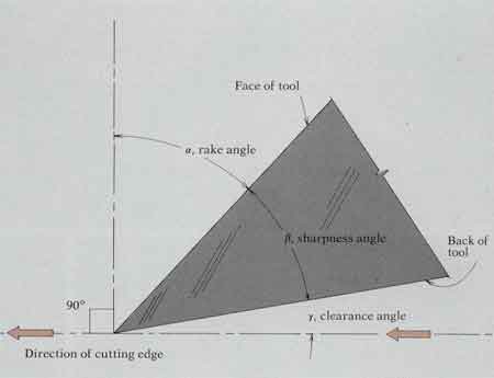
At the business end of a cutting tool, where chips are being formed, the
tool geometry can be described in terms of a cutting edge formed by its
intersecting face and back surfaces, or planes (1). The critical
geometry of the cutting edge is usually defined in terms of its
direction of motion:
î = the rake angle [also called the cutting angle, the hook angle, the
chip angle and the angle of attack) is the angle between the tool face
and a line perpendicular to the direction of travel of the edge. /3 =
the sharpness angle, the angle between the face
and back of the knife.
ó = the clearance angle, the angle between the back of the knife and the
direction of travel of the edge. As required by circumstance,
cutting-tool geometry can be varied considerably. The sharpness angle
will always be a positive value. The cutting angle and clearance angle
can be negative values. In the case of the
between tool and workpiece.
| 1—The business end of a culling tool consists of an edge formed by
ils intersecting face and back surfaces. Its geometry can be described
by the rake angle, î (alpha), measured from a line perpendicular to the
direction of travel to the tool face; the sharpness angle, p (beta),
measured between the face and back of the lool; and the clearance angle,
ó (gamma), measured between the hack of the knife and its direclion of
travel. |
|
Chip formation
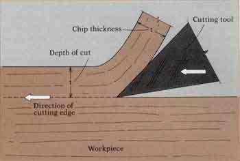
| 2—Cutting action idealized. Energy Is consumed in severing the wood
to form the chip, in deforming or rotating the chip, and in friction of
the tool face against the chip, plus friction of the tool back against
the new surface of the workpiece. |
 |
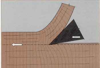
| 3—Cutting action in reality. The wood does not fail until ultimate
stress is reached, and stress is always accompanied by strain. As the
cut proceeds, the workpiece deforms ahead of the tool, severs, and then
both workpiece and chip spring back to some extent. |
 |
Types of cutting action
There are two basic types of cutting action. The first is called
orthogonal cutting, in which the tool edge is more or less perpendicular
to its direction of motion and where the cut is in a plane parallel to
the original surface of the workpiece, with removal of a continuous
chip. An ordinary plane peeling a shaving from the edge of a board is
one example. The second type is referred to as peripheral milling, in
which a rotary cutterhead carrying one or more cutting edges
intermittently contacts the work surface. Each cutter proceeds on a
curved path, and removes a single chip. Virtually every cutting
situation can be compared to either orthogonal cutting or peripheral
milling. Note that as the cutter-head radius increases in peripheral
milling, it approaches orthogonal culling.
Visualize a cube of wood with its sides oriented in the radial,
tangential and longitudinal planes. According to notation reported by
W.M. McKenzie, orthogonal cutting is described by two numbers. The first
is the angle between the cutting edge and the cellular grain direction
and the second the angle between direection of cutting and the grain
direction. Thus there are three basic cutting directions: 90°-0°
cutting, 90°-90° culling and 0°-90° cutting (!). By considering each
type of orthogonal
cutting, some common types of machining can be
understood more clearly.
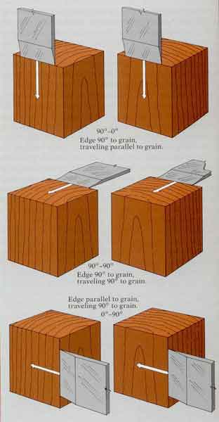 |
| 1—The three types of orthogonal culling. The first number is the angle between cutting edge and grain direction; the second is the angle between direction of cutting and grain direction. |
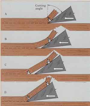
90°-0° cutting (planing along the grain)
Parallel-to-grain culling is best typified by the standard hand plane.
The chip forms as the plane is pushed along the board. The typical
cutting action involves a cyclic sequence of events (2), The iron
separales fibers lengthwise to begin a chip (A). As the knife advances,
the separated chip slides up the iron. The chip is now a cantilever beam
that resists bending. It lengthens itself by failure of the wood in
tension perpendicular to the grain well ahead of the knife edge (B).
Finally, the chip is so long that bending stresses equal the strength of
the wood and the chip breaks (C). The iron advances to the fracture
point and begins to lift ihe next segment of chip (D) and so on. The
chip, produced in a long jointed curl (see Figure /, page 144), is
referred to as a Type I chip in 90°-0° cutting.
The typical plane cutter or iron is set al an angle of 45°. Sharpening
to an angle of 30° leaves a 15° clearance angle. If the rake angle
becomes too great, the friction of the chip upon the iron face would
increase and Ihe efficient bending and breaking action would be lost-
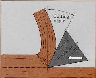
ward compression and ii smaller component of upward lifting are
transmitted to ihe chip. Failure may occur as a diagonal plane of shear,
bending the fiber structure, so curl of deformed cell structure. This is
classified as a Type II chip (3). The cutting edge produces the surface
as it dislodges cell structure. Greater force is required because of the
compression resistance. Where the tool is well controlled and a
reasonably thin chip is taken, chip formation takes place quite
uniformly and an excellent surface is produced. Some special hand planes
with a cutting angle of only about 30° are designed to take
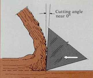
As small (or even negative) cutting angles are used, the grain. The
knife edge produces the surface as it shears free the cell structure. As
the wood fails in compression, the damaged cell structure packs up
against the cutting face and may form a wedge that transmits force and
causes failure out ahead of the knife edge, often below the projected
cutting plane. The failure is erratic and leaves an irregular surface,
and is accompanied by an irregular chip of mangled cell structure. This
is Type III chip formation (4). With very low cutting angles, a smooth
surface and uniformcutting action occur only when a thin enough chip is
taken to form Type II chips. This is the cutting action of scrapers.
 |
|
2—The cutting action in planing wood. The cut begins at A. The chip
bends as it slides up the knife, and the wood fails ahead of the edge
due to tension perpendicular to the grain, B. Finally the chip breaks, С
whereupon the next segment of the cut starts, D. In 90°-0° cutting this
is known as a Type I chip, produced by a relatively large cutting angle. |
| 3—At small cutting angles, the face of the knife produces more forward compression than upward lifting. Failure occurs as a diagonal plane of shear right At the cutting edge. With, enough force and a thin chip, the workpiece surface can be left in excellent condition. This is a Type II chip in 90-0" cutting. |
 |
|
4—At very small (or even negative) cutting angles, force is transmitted mainly as compression parallel to the grain. The damaged cells pack up against the culling face, often causing erratic failure ahead of and below the edge. This is a Type III chip in 90°-0° cutling. The snowplow effect can only be avoided by taking a very thin chip, whereupon it becomes Type II cutting. Cabinet scrapers work this way. |
 |
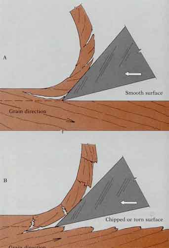
The quality of cutting depends mainly on two factors: the grain direction and the mechanics of chip breakage.
Figure 2 on page 147 assumes perfectly straight grain, which in reality is more the exception than the rule.
Usually some degree of cross grain exists wherein the fiber direction either rises ahead of the projected line
of cut or leads down below it. The former case is termed cutting with the grain, the latter cutting against the grain (I),
Cutting with the grain is preferable, since the splitting of the wood associated with chip formation projects harmlessly into
the next chip segment which subsequently will be removed. The cut produces a new surface generated by the continuous severance
at the tool edge. Culting with the grain is very efficient because most of the chip segments fail readily due to cross grain.
The woodcarver will find that cutting with the grain at an acute angle to the grain is a fairly efficient way to remove large
amounts of slock. At the same time, 90°-0° Type I chip formation using a hand chisel can be painfully undesirable in carving.
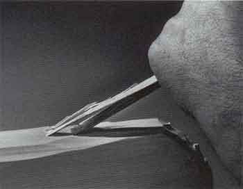
The case in point involves carving with the grain, where a splinter-type
chip slides all the way up the face of the tool and jabs the carver in the
hand (2). I have numerous scars on the outside heel of my left hand thanks
to this situation. I collect another scar every time I fail to wear a glove
By contrast, cutting against ihe grain can result in chip formation where
the splitting projects below the intended plane of cutting. The resulting
surface is called chipped or torn grain. In some cases, as in planing the
edge of a flatsawn board with spiral grain or in passing a flatsawn board
with diagonal grain through a surface planer, the board can be alternately
turned end-for-end so that culling will occur with the grain. In other cases,
however, as with the bulge of grain direction associated with a knot, some
cutting must take place against the grain. To minimize the depth of torn
grain, the breaking length of the chip segments must be controlled. One
approach is to take an extremely thin cut, in which the chip segments break
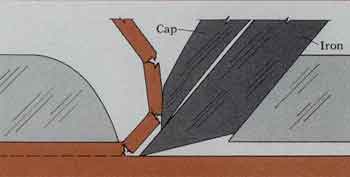
frequently. Otherwise, a "chipbreaker" must be introduced, such as the
cap iron on a hand plane (3). The cap must be located suitably close to the
cutting edge and must fit tightly enough to the face of the iron so the chip
will not lodge but will slide up easily and bend beyond its breaking point
quickly. The Face and mating edge of the cap should be shaped as precisely
as the cutting edge of the iron itself, for the сaр iron is an integral pan
of the cutting mechanism.
The importance of the clearance angle in the cutting process should be
appreciated. As with the "springback" of the wet sponge, it is also true
that some deflected cell structure will recover alter the chip lorms. In
order for the back of the cutting edge to clear this material, fric-tional
drag and pressure against the back of the knife must be eliminated. If the
cutter were infinitely sharp, of course, little clearance would be needed,
and recommended clearance angles of up to 15° may seem excessive. However,
such large clearance angles are probably safeguards against less-than-perfeel
sharpening. If the back (beveled side) of the cutter is not perfectly flat,
the clearance angle is reduced. As will be pointed out in discussing
sharpening, it is crucial that no portion of the cutter be deeper than the
cutting edge itself.
In 90°-0° cutting with a hand chisel, the back of the tool itself guides the
cutting direction. The clearance angle is effectively zero, and springback
is automatically compensated by the angle at which the tool is held.
Frictional resistance is overcome by whatever force is applied to advance
the chisel.
Most hand planes used along the grain involve 90°-0° cutting, whether they
operate on the whole surface of the wurkpiece (as in planing a flat surface)
or whether they plow a groove or form a rabbet. Spokeshaving down a canoe
paddle is another example of 90°-0° cut-ling where tool geometry and depth
of cut are fixed by tool design and adjustment. Rough-shaving an ax handle
with a drawknife and taking long shavings along the grain with a pocketknife
are also 90°-0° cutting; in these cases the cutting angle, clearance angle
and depth of cut are controlled by the way the tool is held.
 |
|
|
1—In ihe real world, the wood grain is rarely parallel to the cutting
direction Usually ihe fibers are rising ahead of (he line of cut, and
cutting with the grain leaves a very smooth surface (A). When the Fibers
lead down below the line of cut, cutting against the grain leaves a chipped
surface (B). We usually reverse either the work or the tool, to go with the
grain. |
 |
|
| 2—In woodcarving, ihe splinter-type chip resulting from 90-0° cutting with ihe grain can slide up the tool face and jab an unwary carver In the hand. |
|
3—In 90°-0° cutting with a hand plane, the cap Iron minimizes frorn grain by
breaking the chip near the cutting edge. |
 |
Peripheral milling (machine planing)
Orthogunal cutting in the 90°-0D mode has a counterpart in peripheral
milling in the cases of the typical jointer, single surfacer, spindle shaper
and router— wherever a revolving cutterhead operates along an edge or face
of a board.
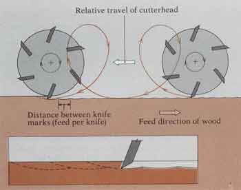
The cutting action is modified by the path of each cutting edge, which by
combined revolution of the cutter-head along the surface of the workpiece
follows a trochoidal path (1/. Each cutting edge takes a curved chip from
the workpiece. Customarily, rotation of the cutterhead moves each knife in a
direction opposite ihe relative direction of the workpiece, representing the
up-milling condition (1, inset). In most rotary cutterhead designs the
cutting angle is decreased to between 10° and 30°. This requires more power,
but the chip type produced approaches a scraping Type II or Type III chip
rather than a splitting action, as in Type 1 chips, and there is less
uncontrolled splitting ahead of the knife edge. The surface generated by the
overlapping cutting arcs of successive edges is wave like. These waves are
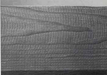
often visible and are known as knife marks. Figured shows an extreme case of
knife marks in crudely planed structural lumber—only four to the inch. The
marring of the surface is plainly visible. However, in finish lumber the
best surfaces are produced by 12 to 25 knife marks per inch. In this case,
the height of the waves is typically quite small, and may not be seen easily
with the naked eye. Their visibility is the result of crushed or buckled
cells, rather than the actual surface irregularity of the waves (3). When
the number of knife marks per inch exceeds 30, unless the culling edges are
extremely sharp, the surface may actually get worse. The chip gels so small
that each cutting edge does not bite, but rather rides over the surface, as
with the table knife and ihe wet sponge. Frictional heat also may be
produced and the resulting surface, although apparently smooth,
|
|
 |
|
1 In peripheral milling, each cutter actually follows a trochoidal path relative to the work piece, the result of culter-head rotation plus feed. Each cutter takes a curved chip from the workplece, usually by up-milling (inset). |
 |
 |
| 2—Crushed cells delineate knife marks—about fc.ur lo the inch—on this eastern hemlock board. |
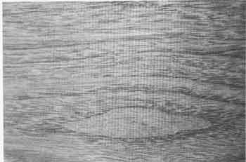
3—Light reflection reveals closely spaced knife marks on this butternut board |